AHand is an electrical engineer working for a company that integrates solar photovoltaic systems as a temporary job until he starts his PhD. This week, he sent us a nice article focusing on the visual inspection of Medium voltage switchgear during testing phase.
Check his work below and send us a mail if you want your articles to be published in this blog.
Medium voltage switchgear: site acceptance tests
After switchgear erection, installation, control wiring assembly on-site and before connecting any cables from the plant, the switchgear must be admitted to the site acceptance tests (SAT), which assures the correct operation of the switchgear according to specification before energizing it. SATs are derived from the International Electrotechnical Commission (IEC) standards 60694 and 62271-200.
The process for a SAT consists of seven important steps, (1) the visual inspection, (2) the functional tests, (3) the mechanical tests, (4) the measuring devices tests, (5) protective relays tests, (6) the dielectric tests and the (7) insulation resistance tests.
The SAT is basically the same for different switchgear configurations, but the tested functions may vary from one switchgear configuration to another. For example, some switchgear configurations include a synchronization check function between the incoming cubicles to synchronize the coupling of two different power sections, or other configurations include special protection functions for the outcoming cubicles, so for each case the different functions should be tested.
Before working, the commissioning engineer from the contractor or manufacturer’s side should look at the drawings and prepare the test equipment to be delivered on-site and estimate the manpower needed to complete the job in due time. From the customer’s side, the switchgear must be cleaned from any dust, the area should be made clear of obstacles and the customer should provide the 230 VAC and 380 VAC power supplies necessary for the testing equipment.
A meeting is usually held between the consultant, contractor (or supplier) and customer before the tests to agree upon the details of the test procedure and the documents to be signed and the certificate forms.
On-site and after the documents have been prepared, all safety measures must be taken, barriers should be set around the switchgear, the switchgear must be properly earthed and only authorized personnel from the three main parties should be allowed on-site.
Medium voltage switchgear: visual inspection
The first step is to inspect the switchgear visually by comparing the drawing with the actual installed items. Visual inspection is important because (1) it ensures that the switchgear has been manufactured according to the drawings and specifications and (2) it helps in identifying some problems that might have not been realized during the factory acceptance test (FAT).
In some cases, the labelling might be wrong or some component might be missing or one might even discover a loose connection. In the visual inspection process one should scan his eyes through as much details as possible, because there might be a missing label, a missing gasket or a spot that needs to be repainted or any other detail.
To prepare for this test one needs the single line diagram (SLD), the control wiring, a pencil and highlighter.
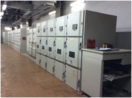
Examples from the field
As mentioned above, the visual inspection can identify some serious problems, which could save a lot of time and effort, in the following figure, the ammeters are connected to the measuring core of a current transformer, imagine if one of the connections is loose, what do you assume will happen when the 11 kV and the 1000 A are subject to the primary core? It simply is the textbook case of an open current transformer circuit which can cause arcing or even explode. So, it is good practice to give the current transformer circuits some extra attention and in this case check that the wires are properly fixed into the ammeters.
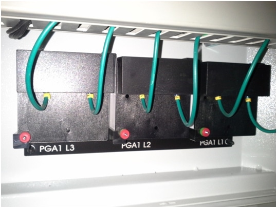
Figure 1 A loose ammeter connection means that the current transformer has a core with an open circuit, one should look carefully at current transformer connections to avoid serious accidents
Sometimes the installed components are not the specified ones, so it is good practice to take a close look at the labels of the main components at least. In the following figure, the installed current transformer has core ratios of 200/5 A, while the specified ones are 300/5A.
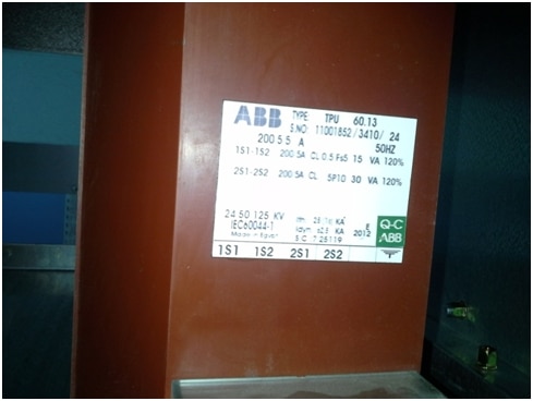
Figure 2 Checking the labels visually before going through the test procedures is important to make sure the correct components are installed; the tests can be a nightmare if they give unexpected results
In some cases, the components are ordered correctly, but some functions specified for the component are missing. This is quite common with protection relays, because they usually have too many functions.
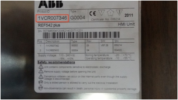
Figure 3 Checking the product ID of protection relays assures that the correct relay has been ordered as specified with all the requested functions
In some cases, the mimic diagram on the cubicle might be incorrect, the indicating leds might be misplaced or incorrectly labelled, or a pushbutton might be broken, so it is good practice to check and compare with the drawings.
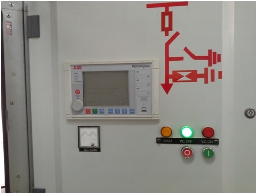
Figure 4 Checking the mimic diagram, indicating lamps, push buttons flag relays and comparing with the drawings to make sure they are placed according to specification
The cubicle nameplates can sometimes be labelled with wrong names or misspelled, so it’s worth checking and comparing with drawings.
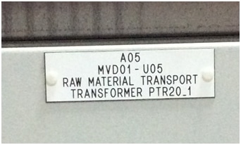
Figure 5 Cubicle nameplate might be labelled with wrong name or misspelled
Conclusion
In this article, we went through the process of testing medium voltage switchgear on-site and we dedicated this first article in the series to the visual inspection test. In the next article the functional tests shall be discussed.
For further reading refer to,
[1] IEC 62271-200:2011 webstore.iec.ch/publication/6716
[2] IEC 60694:1996 Common specifications for high-voltage switchgear and controlgear standards, webstore.iec.ch/publication/17249
Thanks for reading,
AHand.
What do you think of these testing principles? Do you have more to share about it? Please comment below.
Please send me link to read full article including functional tests and remaining portions.