
As Milan talked earlier, aircraft generators are essential part of aircraft electrical system. Briefly, he mentioned two main types of AC generators, one is constant frequency and another is variable frequency generators.
Now, he’s going to dive deeply in working principle of one most common generator – brushless generator.
Standard generators are bitten from brushless
Classic use of brushes and slip rings for passing excitation current to AC windings made huge problems due to brush consumption and during the time rotating surface make traces on rotor of generator. Also, power that is conveyed is smaller that in brushless type.
Overview of this generator is given in Picture 1. Mostly, it is made with three main components:
- Exciter
- Rotating rectifier
- AC generator
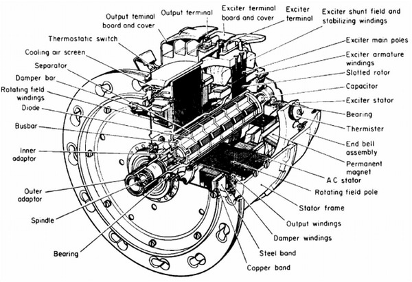
Picture 1. The brushless generator
These three components are mounted in one case. The exciter is located on the other side from input rotation section. This is called bell sector of generator, and it is consisted of stator and three-phase rotor in star connection. Armature of exciter is located on the same shaft as main generator rotor and the result of excitation is feeding rectifier assembly. In the practice this excitation is made of three stages. Firstly stage is described above, and it is 50V/800Hz.
After these first pace of excitation, the rotating rectifier supplies current to the main rotor and their field coils. This is second stage of excitation, and there is the main difference form standard brush generators. Here we have AC current for main rotor field coils.
Finally, generator consists of three-phase star wound stator and rotor with 8 poles, which is connected to field windings and linked to the output of rotating rectifier. Further, three stator phases are brought directly to the upper surface of an output terminal board, and conduct the three phase electrical current to the aircraft. Alongside to this field coils, we have additional windings mounted on rotor. The main usage of this windings is to ensure an induction engine effect on the generator, due to rapid changes of load. This is important because when we have dis-balance of rotor speed the frequency will vary.
Also, in normal operational, this additional windings will reduce transient voltages made from line system faults, and will decrease voltage unbalance during the line unbalanced load. Picture 1. presents one brushless generator.
How can we generate enough rpm?
All this process of generating AC current is located in bell sector. Also, the drive is important part of this device. The main rotor shaft consists of inner, outer and spindle adaptors which are fitted to a stub shaft and connected to the main generator rotor.
Approximately, input values are 4000-7000 rpm and output is constantly 12000 rpm. So, this mechanical device takes variable input and gives constant output, and working principle is based on hydromechanics. This type of generator is commonly use in turbojet aircraft. Input rpm are given from aircraft engine. The working principle is based on hydromechanics and on its input is variable ratio drive.
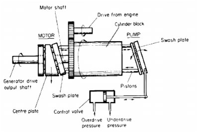
Picture 2. Working principle of constant drive speed unit
On the other hand, variable input rpm are regulated with hydraulic pump and a permanent rotating of plates type of motor. The system is in connection with compressed low-pressure from engine which gives pressure to the oil system and close the charge of pump. At the end this hydraulic system with rotating plates gives on its output constant value of 12000 rpm. Working principle of one constant speed drive is presented on Picture 2.
What would be the main problems?
The main problems of this generator type is regulation of pressure and temperature. This type of generators have electro-mechanical disconnect system. In case of mechanical malfunction, when rpm are out of range and too high for normal operation mode, the mechanical part of generator is disconnected form bell side. The working principle is shown in picture 3.
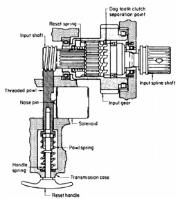
Picture 3. Disconnect mechanism
When failure occurs the solenoid is activated and spring-loaded pawl moves and make separation of driving dogs of the clutch. This failure can be reset only on the ground. The procedure follows pulling out the reset handle, and then withdraw the pawl from input.
After that the spring on the shaft is re-engage the clutch. Finally, the solenoid is de-energized, and its pin is fill into the position of slot in the pawl.
Conclusion
The powerful aircraft electrical system must be confident and reliable. The brushless AC generators have enough power for AC distribution and ensure the continuous work of all elements and system that are connected to the distribution.
In the table below you can see characteristics of one standard brushless generator which is used in one modern turbojet aircraft.
| Type: | Brushless generator/constant drive unit |
| Support AC current: | 3 phase / 400Hz |
| Power: | 30 kVA continuous / 60 kVA for 30 sec |
| Supported standards: | MIL 704F/ MIL – PRF – 21480 |
| Normal operational frequency range: | 385-415Hz |
| Voltage operational range: | 115V phase-N/208V between phases |
Thank you for your attention,
Milan.
What do you think about this topic and its link to aircraft?
Thank you for sharing good information. keep sharing..