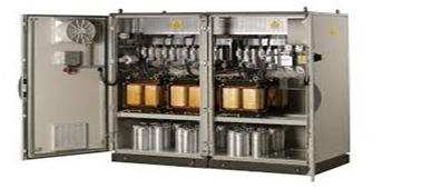
Harmonic filter banks are vital components in an electric system. The primary purpose of the banks is to provide an alternate low impedance path for harmonic current, thus reducing the amount of harmonic current in a distribution system. When purchasing the banks, the primary consideration for the engineer is to understand the primary difference between the actual and installed kVAR.
This article by our member Marvin M. provides a guide on the difference between the two as well as why understanding the two distinct values is important when installing harmonic filter banks.
Understanding the Difference Between Actual Versus Installed KVAR
For starters, note that the harmonic filter reactor does result to significant rises in voltage. About a decade ago, most applications of low and medium voltage consisted on linear loads. This means that resonance was uncommon, and a simple addition of capacitors did suffice as a power factor correction measure.
Nowadays, however, non-linear loads and variable speed drives are very common. These loads, which include motors, mills, battery charging equipment and invertors introduces harmonics into the systems by generating non-sinusoidal current from sinusoidal voltage.
Engineers usually recommend a series reactor to sort out the resonance problems. Though capacitors are designed to absorb reasonable amounts of harmonics, the peaks and excessive harmonics in an industry utilizing medium voltage equipment can lead to voltage rise and eventual break down. This is easily expressed using the following formula.
Vrise=N²/ (N²-1)
Vrise is the voltage rise while N is Filter Bank Turning point
Application of these variables means that when the tuning point is decreased, the voltage rise increases. To accommodate these scenarios, the capacitors used should be rated higher than the system voltage. The three primary tuning points are detuned filters(between 4.0 and 4.4),partially tuned(4.4-4.8), and tuned filters (4.8-5.0).
- Detuned filters are used primarily for power factor correction. They are the cheapest options. However, they do little to sort out any harmonic distortion.
- Partially tuned filters are used in cases where power factor correction is required, as well as sort out excess distortion levels.
- Tuned harmonics are used when the sole objective is to bring down the distortion levels to acceptable levels. They however require precise engineering design due to the high risks associated with drawing harmonics from the industrial and local utility system.

Harmonics Filter Bank
Harmonic Voltage Rise
As highlighted, the filter capacitor is rated lower than the nameplate rating (in most cases, the installed kVAR is 20%-40% more than the actual kVAR output to accommodate the voltage rises). Thus, proper understanding of the following terms comes in handy in equipment selection and installation.
- Effective kVAR- the harmonic filter bank kVAR output at a specified system voltage. Ensure that you specify this value when selecting the filter banks for installation.
- Actual kVAR- installed kVAR in the filter banks. This rating is usually left for the manufacturer to specify. The engineers on their part have to ensure that the available capacitor kVAR and the voltage rating are suitable to optimize filter capability.
Conclusion
In conclusion, given the variables that make up an optimised and working harmonics filtering installation, the following elements are fundamental in the final decision-making.
- Harmonic filter bank tuning point
- Filter bank effective kVAR
- Capacitor voltage and kVAR rating
- Justification for capacitor voltage determination
Marvin M.
What do you think of this guide? Would you add or correct some things?
Dear Sir,
Good day!!
How we can calculate effective kVar output of detuned filter if we have 12.5 kVar 7% detuned reactor and 15.5 kavr 480V capacitor ?