Accurately measuring the insulation of an electrical equipment is essential to ensure the operation of the system and to comply with security standards as well.
Therefore, as discussed previously in the Megger vs Doble article, the Doble measurement instrument is the ideal to perform regularly maintenance insulation tests on any transformer, circuit breaker, switch and motors.
In this article, we will examine the basics to understand how to use this instrument.
AC Model of Insulation
As discussed previously, in order to accurately establish the insulation state of a transformer, it is necessary to consider the AC model of insulation. This model can established as an arrangement of impedances connected between them to represent the insulation from one potential point to the other. In other words, wherever there is a potential difference in the transformer, then there an insulation associated and therefore a corresponding impedance.
There are two ways to model this impedance. One way is through the series model and the other is through the parallel model (see figure 1). Any of the selected models can represent the insulation of the transformer, but the typical and practical model is usually the parallel model, as it allows to represent the reactance and resistance with the same voltage.
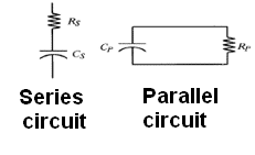
Fig1. Insulation Impedance models
For the parallel model, the following expressions apply:
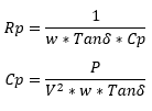
Insulation parallel model
Where,
Rp: Parallel Resistance of impedance
Cp: Capacitance of impedance
w: 2πf
f: frequency (60Hz / 50Hz)
Remember these expressions as we will use them later.
Insulation Test with the Doble
Now let’s take a look at the measurement options that the doble allows us to use. The first thing that you must know is that the instrument has a voltage terminal, two auxiliary cables (typically red and blue) and a ground cable as well. It is also important to understand that the Doble has three measurement modes:
- Ungrounded Specimen Test (UST): This feature allows you to measure the insulation between two differential points without measuring the current that goes to ground. In other words, the UST only measures the current between the two selected options
- Grounded Specimen Test (GST): This option measures the current flowing from the voltage terminal to ground and if it’s possible to another point as well (selected auxiliary cable)
- GST No Guard: This option measures ground current and current flowing towards two terminals (current towards both auxiliary cables)
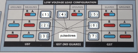
Fig 2. Doble Pulse option
To better understand the push buttons options in the Doble, we will describe them as follows:
UST
- Push 1: Measures the current flowing from the voltage terminal towards both auxiliary cables (blue and red)
- Push 2: Measures the current flowing from the voltage terminal towards the red auxiliary cable. Blue is not measured
- Push 3: Measures the current flowing from the voltage terminal towards the blue auxiliary cable. Red is not measured
GST
- Push 5: Only measures current to ground from the voltage terminal. Blue and Red auxiliaries are not considered
- Push 6: Measures ground current from the voltage terminal, plus the current flowing towards blue auxiliary. Red is not considered
- Push 7: Measures ground current from the voltage terminal, plus the current flowing towards red auxiliary. Blue is not considered
GST No Guard
- Push 4: Measures ground current from voltage terminal, and current flowing to red and blue auxiliaries
A simple way to understand this is by taking a look at figure 3. The H terminal represents the voltage terminal (which can be placed in one of the bushings of the transformer).
Terminals R and A are referred to the auxiliary cables. If the UST feature is enabled, then the lower switch to ground is opened, on the other hand, if GST is enabled, then is closed. When one auxiliary cable is not measured (Guard – GST or Ground –UST) then the switches located below the voltmeter close.
When an auxiliary cable is to be measured, then the switches below the terminals R and A in the figure, are closed:
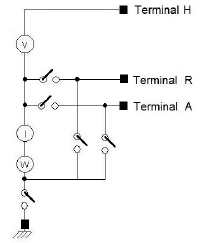
Fig 3. Model of Doble instrument
Now that you know how to use the Doble, let’s remember the expressions that we mentioned before as they will allow us to find out the impedance values of our insulations.
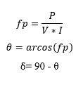
When you select one of the options, the instrument will show you three values: Power, Current and Voltage. Based on these parameters you are able to establish the impedance value between terminals by using:
Where,
Fp: Power factor
P: Power measured
V: Voltage measured
I: Current measured
θ: Phase angle between V and I
Tanδ: Dissipation factor of insulation
Using these expressions and the ones of Rp and Cp, you can calculate the impedance of insulation between any terminals of a transformer by:
Establishing the insulation between bushings, (phase to phase) and from bushing to ground are the most usual measurement. Once you have your insulation values, you must compare them with the datasheet of the transformer and check that the values are within expected range.
Thanks for reading, do not hesitate to comment below.
Steven Mill.
