Home › Electrical Engineering Forum › General Discussion › VAR & Its Applications
- This topic has 2 replies, 2 voices, and was last updated 10 years, 3 months ago by
Anonymous.
-
AuthorPosts
-
2013/04/10 at 3:52 pm #10986
Steven Mill
ParticipantThe Premise
When there is a higher current flowing through the transmission line, there is a problem with the increase in transmission loss. With more current flow, there is a problem with heat generation. This also causes an increase in the resistance as well.
VAR Compensator
The abbreviation VAR stands for Volt Ampere Reactive or as commonly referred to as the reactive power. The purpose of this device is to provide a rapid reactive power in the case of high voltage electrical transmission networks. Such devices are generally the part of regulation and stabilization. For instance, they are an integral part of the flexible AC transmission system device family.
As far as the physical construction is concerned, there are no major rotating parts. This is different from the case of a synchronous condenser where there is a rotating part (electrical machine). The synchronous model was used previously and in combination with capacitor banks accounted for the power factor compensation.
Situational Usage
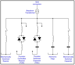
We are now clear that a Static VAR Compensator (SVC) can be summed up as an automated impedance matching device which allows the system to approach the desired goal of a unity based power factor. The usage of such a device occurs in the following scenarios:
- Regulation of the transmission voltage by being connected to the power system. Such usage is referred to as the transmission SVC.
- Improvement of power quality by being connected in close proximity to large industrial loads. Such usage is referred to as the Industrial SVC.
The Need for reactive compensation
The mathematical calculation of reactive power indicates that it is a product of voltage and current (when the phase difference between voltage and current is 90°). From this derivation it is quite obvious that the flow of reactive power changes in each quarter of the cycle. This is opposite to how the active power behaves, which is unidirectional. In terms of practical application, the current (reactive) flows and this is what results in the existence of line losses.
This issue is compounded on the account that the loads are drawing lagging power. This has an overall sagging effect on the electrical power system voltage. When the loads are on the lighter side, the effect is in the reverse and leads to a surge in the voltage. The logic is quite clear in the sense that we need less reactive power, so that more active power can flow through the system.
The Idea of Compensation: Mechanical and Static
It is a general practice of installing capacitors for compensation. They are usually installed from line to ground and cater to the lagging reactive power. For compensating leading reactive power, reactors are connected line to ground. As the line loading varies throughout the day, there is mechanical control of reactor and capacitors being switched on and off. This brings out the issue of reliability of the control owing to its frequent usage.
This is where the static VAR serves as an efficient alternative. These devices have static switches which are known as thryistors and increase the reliability of the device. The only low side is that such devices are expensive, so one may to have bring in the cost versus working efficiency factor here.
Advantages of VAR Compensator
Following are some of the main advantages of a VAR compensator:
- The response is faster and the adjustment is instantaneous.
- On a large scale, SVC’s can be cost effective on the account that they are reliable.
- They can handle larger power capacity units.
- The instantaneous response is much faster than those seen in the case of mechanically switched compensation designs.
Review of Modified-VAR
- AMSC’s Dynamic-VAR
This device is able to operate dynamically and perform the task of provision of grid support. The responses occur in real time and are rapid. It is optimized for usage in the case of T&D networks and also for industrial operations. It directly acts on the transmission and distribution grids and compensates for leading and lagging reactive power. The good thing about this solution is that it can be customized to suit the user’s need and as per their electrical systems.
- Design of D-VAR systems
Another added advantage of this device is that it offers higher level of modularity and scalability. This means that you will have the size which is needed for your location. It has room for adjustment and modification as you expand your plant. There is also no problem with usage where the space access is on the lower side.
Conclusion
A holistic view of the static VAR design along with its pros and cons has been discussed. Comparison has been drawn with the mechanical model on the account of functionality and usage. It is quite clear that the static option is more dynamic for the electrical system. However, the cost factor is something that does interfere with the design. An ideal solution that is opted for by many units in such a scenario is to use both of these compensators. In this way, the static compensator accounts for the rapid changes whereas the mechanical compensation caters for provision of steady state VARs.
2014/08/30 at 7:45 am #13540Anonymous
GuestI have learn a few just right stuff here. Definitely worth bookmarking for revisiting.
I wonder how so much effort you put to create such a fantastic
informative web site.Look at my web page; AC Repair Palm Springs CA
2014/08/30 at 8:48 am #13541Anonymous
GuestThank you for some other magnificent post. The place else may anyone get that type of information in such a perfect method of writing?
I’ve a presentation next week, and I’m at the search for such information. -
AuthorPosts
- You must be logged in to reply to this topic.


