Your fellow electrical engineer Jesús Pérez Díaz is back with a great new article featuring a video tutorial (ETAP software). Enjoy!
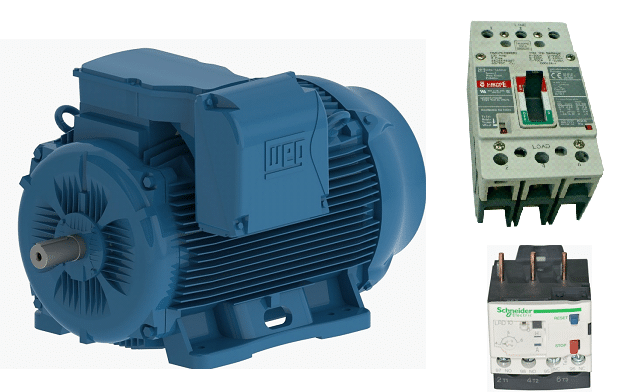
250 hp WEG motor / HMCP Cuttler Hammer / Overload Relay Schneider Electric
Hello everyone! In this article I want to show you how to determine the protective device settings of a typical and simple protection scheme usually applied to low voltage motors, considering the electrical protection basis and using ETAP (Electrical Transient and Analysis Program)to build the time-current curve.
Introduction
Electrical motors are found in all kinds of industry and applications, going through a small water pump to a critical belt conveyor of a manufacturing plant.
The protection system must aim to protect the motor (also cables, contactor, and any feeder equipment) against any damage and keep healthy the remaining electrical system by means of clearing the fault as quickly as possible, but discriminating the normal motor operation from faults, e.g. electrical motors used for general purpose are usually designed as NEMA B; for these kinds, the locked rotor current (LRC) is around 6 times the motor full load current (FLC), so the protection system must allow the starting (even though the starting current is 6 times greater than normal) and only trips if the motor starts to be damaged.
In addition, the selection of the protection scheme must take into account: the criticality level of the corresponding process, motor repair costs, loss costs due to the out of service, power and voltage ratings, applicable standard, guidelines and Client accepted practices.
As a result, the selected scheme may be really simple or more sophisticated, including specific protection functions such as: ground fault, locked rotor, differential, successive starts, unbalance, etc. (Some of these special functions will be explained in upcoming articles).
Typical protection scheme of a LV motor
A typical protection scheme applied to a Low voltage motor is shown in the figure 2.
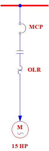
Figure 2
This scheme includes the following protection devices:
1) Motor Circuit Protector (MCP)
MCPs fall within the classification of Molded Case Circuit Breaker (MCCB). They only have instantaneous trip (magnetic) for the purpose of protect motors against short circuits.
The setting of the MCP tripping must be enough to allow the motor starting but lower than the minimum available short circuit current. The National Electric Code (NEC) establishes in section 430.52 (C) (3) that the pickup current shall not exceed 1300% of the motor full load current (FLC). Additionally, the setting must take into account the asymmetrical component of the starting current which could be considered as 150% of locked rotor current (LRC).
For a general purpose motor, designed as NEMA B (starting current around 6 times FLC), the setting should be:
2) Overload Relay (OLR)
MCP does not protect the motor against overload, so an OLR is needed in order to avoid any damage. The OLR can be thermal type (rarely used these days) or electronic type, connected direct on line or through current transformers.
Nowadays, due to technological progress a simple motor OLR can have a lot of control and protection functions, but I would like to focus only in the thermal overload protection (49). The National Electric Code (NEC) establishes in section 430.32 (A) that the pickup current for motors rated as 1 hp or more with a service factor of 1.15 or greater shall not exceed 125% of the motor nameplate full load current (FLC) or 115% for service factor of 1.
In most cases, motors are oversized due to the load factor applied by mechanical/electrical discipline (80%-90%), so an overload of 25% should be a failure condition for sure. My personal comment is that any overload greater than 115% should not be allowed, and only special applications where the motor was sized using a detailed method (such as RMS torque) should be studied in order to define the overload value to be allowed.
By the way, it is important to highlight that where a power loss would cause a hazard, the overload protection must not be considered (e.g. firefighting pump).
The above rules for determining the pickup current are general and should be evaluated for each case, also they must be adjusted according to motor damage curve, motor starting curve, cable damage curve, contactor damage curve, and calibrated by field tests
Sample Calculation
Based on the scheme shown in figure 3 and the following data, determine the preliminary settings for MCP and OLR. Use ETAP software to draw the corresponding time-current curve.
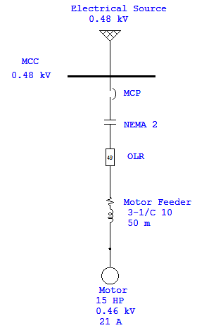
Figure 3 (Created on ETAP software)
Data:
- Voltage: 480 V (3 phase, 60 hz)
- MCP: Brand: Eaton / Cutler-Hammer, Frame: F (150 A), model: HMCP050k2
- OLR: Brand: Square D, Model: Motor Logic, Class 9065, SS210, solid state on line connection
- Motor: 3 phase, 460 V, 15 HP, FLC: 21 A, LRC: 600% FLC, Stall time (hot): 12 sec.
- Motor feeder: 3 x 1/c #10 AWG, 50 meters.
Calculation:
- MCP current pickup
Ipickup (MCP)≈1000% FLC=10 x 21 A=210 A
Ipickup (MCP)< 1300% FLC=13 x 21 A=273 A
Consulting the MCP manufacture brochure:
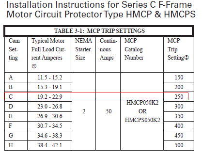
Figure 4: Installation Instructions for Series C F-Frame Motor Circuit Protector Type HMCP & HMCPS – EATON document: IL 29C401J
Letter “C” should be selected and set in the MCP:
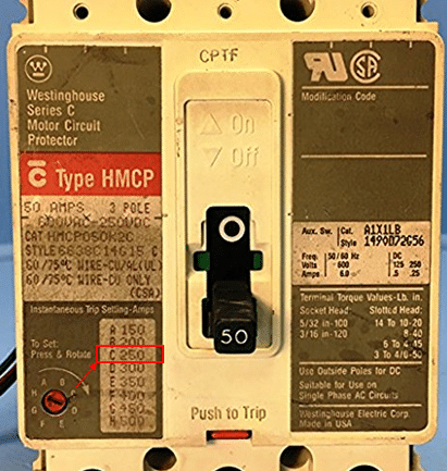
Figure 5 | image: https://images-na.ssl-images-amazon.com/images/I/51Mc4Qj0ibL._SX466_.jpg
- OLR current pickup
Assuming a motor service factor of 1, the current pickup will be:
Ipickup (OLR)=115% FLC=1.15 x 21 A=24.15 A (Maximum)
Consulting the OLR manufacture brochure:
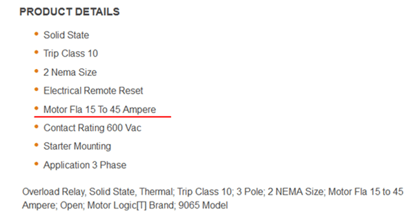
Figure 6 | image: cesco.com
Construction of the Time-Current Curve on ETAP software
The final curve considering the settings already calculated is shown in figure 7.
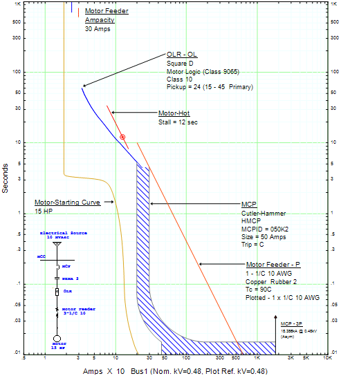
Figure 7: created with ETAP software (video tutorial below)
Jesús Pérez Díaz
Submit your comments below, Jesús will be glad to exchange with you all!
I like it
Thank you