Introduction
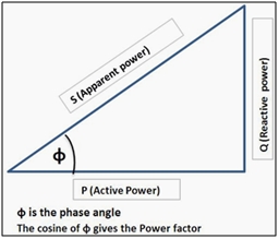
In an AC circuit, there is a likelihood of interrupted direction reversal of the energy flow because of the temporary energy storage in inductive and capacitive parts.
The real power is the power flow left after it has been equally distributed in an AC waveform which in actual can be further utilized to do work such as heating an element and to overcome friction in a running motor.
However, the reactive power is the power flow which is due to the inductive and capacitive network elements; it is first temporarily stored and then returned back to its origin.
Inductors consist of a large coil and are devices which have the capability to store energy in form of magnetic field. On application of voltage, magnetic field is produced across the coil and after some time the current attains its full value. The voltage, so, surpasses the current in phase. Such devices are said to be the ones absorbing reactive power.
Energy storage in form of an electric field is the work of a capacitor. Full voltage difference is reached in some time until a charge is built up when the current is driven through the capacitor. As a result, fluctuation in voltage through the capacitor is observed which is opposed by it causing the voltage to fall behind current in this case. This is therefore referred to as the generation of reactive power because the voltage experiences drop back from current this time.
Reactive power flow occurs due to the energy storage in network inductive and capacitive elements. Voltage level is greatly affected by the reactive power flow throughout the network. As a result there is a need to properly monitor and manage the voltage level and reactive power flow so that the network operation is held within appropriate limit.
Key points involving reactive power and voltage control
Key points involved in this matter include:
- The voltage received by the equipment linked in the system does not surpass a specific limit.
- The stability of the system, largely affected by control of voltage and reactive power, is increased which allows for the maximum usage of the transmission system.
- The efficiency of the transmission lines is made guaranteed by reducing the flow of reactive power so that the RI2 and XI2 can be decreased to a practically minimum level.
Specific devices are distributed across the system for voltage control because reactive power transmission is least likely to occur over greater distances. The main challenges to achieve the above key points are choosing and coordinating the proper equipment.
Reactive Power: Production and Absorption
The production and absorption of the reactive power can be achieved with the help of a number of devices including synchronous generators, overhead lines, underground tables, transformers, loads, shunt reactors and synchronous condensers.
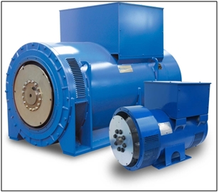
The role of synchronous generators as a generator or an absorber is highly dependent on the excitation. Over excitation results in the generation of reactive power, while under-excitation results in absorption of reactive power. Field current, end- region heating limits and the armature current are the three limiting factors of the ability of the synchronous generator to produce or absorb the power.
By controlling the excitation of this device the armature voltage can be managed. The management of excitation is so important which is done by automatic voltage regulators fitted in the synchronous generators. Overhead lines function to produce reactive power when the load is below the natural load while in case of vice versa situation it acts as absorber of reactive power.
Loads have the capability to function as absorbers of reactive power only. Voltage magnitudes have been found directly related to the variation in the load. The purpose of shunt reactor installation is to control the rise in voltage during an open circuit or light load. A shunt reactor should be attached with the transmission line at all times and of an appropriate size so as to regulate the temporary increase in voltages due to variation in fundamental- frequency. The aim is to control voltage around 1.5 pu for less than even a second.
Heavy load on the transmission might lead to the disconnection of some reactors. Synchronous condenser is not known to depend on availability of a chief mover or a mechanical load. Its ability of generating or absorbing reactive power also depends on excitation of the field.
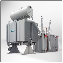
Application of Tap-changing Transformers
Tap-changing transformers are those which allow controlling the voltage running through the system at all times. They help control the flow of reactive power between sub-systems. The voltage to be changed must be of general level so that a synchronized control of tap changers of all transformers should be achieved. Under excitation of generators during light load conditions is prevented by keeping the network voltages low.
Suitable voltage reports can also be maintained using off-load-tap-changing transformers. System expansion, load increase and seasonal changes have to be considered while adjusting the settings of these transformers keeping in mind the long-term alterations.
Mostly loads in any industry are of inductive nature on LT side. For operation & control of big manufacturing plants in the electrical room it contains MCCs and PCCs. It is desirable that the consumed load should be nearer to Unity power factor. so that company stay away from the penalty given by Electricity Board.
But how to overcome the lagging effect so that system can use effectively and efficiently delivered power by Electricity board.
Here is the solution.
With the use of capacitor bank. In industries this scheme is adopted as a APFC Panel (Automatic Power factor Control).
How to determine the rating of capacitor need to connect?
Here is the calculation.
Qc = P ( Tan@1 – Tan@2 )
P= power in kilowatts
Qc= Required reactive power in KVar
Cos@1= operating power factor of system
Cos@2=Required power factor for system
@1= operating power factor angle
@2= required power factor angle
Whatever ans u’ll get is the rating of your capacitor bank need to connect across the load to achieve nearer unity power factor.