 Transformers are static machines that allow the elevation, reduction or equalization of current and voltage without varying the frequency of a system, this is why their operation in the electricity network is essential (generation, transport, and distribution).
There are different types of transformers, which can be classified according to their level of stress, operation, location, construction, and configuration.
Since such machines are distributed throughout the grid, it is required to practice proper operation to ensure that the energy reaches to the customers effectively. This is why during manufacture, installation, and operation, it is needed to perform a set of measurements to assess their condition.
The present article has the purpose of illustrating the most common measurements in transformers. The first thing to consider is the type of transformer because according to its characteristics the most favorable conditions for the tests will change.
Transformers Measurements: relative polarity tests
Among the most common measurements that can be made to transformers we can find relative polarity tests.
They allow to verify the connection of the transformer and determine the relative current flow direction between the high and low voltage windings.
There are various methods to execute this test. The most accepted one consists on connecting adjacent terminals of the windings, then applying a voltage to any of the coils and measure the resulting voltage on the opposite side, as it is shown in image N ° 1.
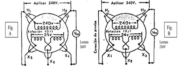
Image N ° 1: Configuration to determine the relative polarity of a transformer | Source: http://1.bp.blogspot.com
If the voltage measured between the other two terminals of the windings is greater than the high voltage side, then the polarity is additive (figure A). On the contrary, if the voltage measured between the two terminals of the windings is less than the high voltage side, then it is subtractive (figure B).
This measurement is important to establish the correct connections of the transformer when coupling it with others in parallel, otherwise, it can cause damages to the machine. This is because the magnetic fields cancel each other and create a short circuit current.
Transformers Measurements: isolation tests
By using a megohmmeter it is possible to measure the insulation resistance of the transformer. There are three typical measurements: Primary winding to ground (case), secondary winding to ground, and a connection between windings.
The measurement is performed in times of 30 seconds and 60 seconds to determine the dielectric absorption ratio (DAR for short) such as shown in the picture No. 2.
The values of DAR are tabulated in the standards COVENIN 3540: 2002 and indicate the state in which the insulation of the transformer is located and its tendency to deteriorate.
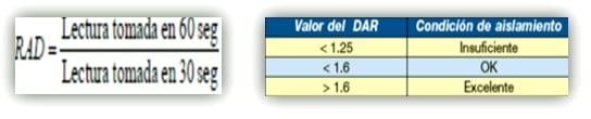
Image N ° 2: Dielectric absorption ratio and insulation conditions | Source: sencamer.gob.ve
It should be mentioned that the insulation is affected by environmental factors (temperature, humidity, dirt, etc.), which must be considered for greater accuracy in the results.
Transformers Measurements: winding resistance test
It allows to determine the power losses due to the Joule effect (I2*R), to evaluate the temperature in the windings and the state of the field.
For this, we must use instruments such as a thermometer and micro-ohmmeter. In addition to that, a series of environmental conditions must be met in order to minimize errors in the measurement.
The test consists of connecting the micro-ohmmeter to the windings of the transformer and measure the resistance on the high-voltage side and then on the low-voltage side. Temperature values for each case must be taken simultaneously, to finally interpret them by using the expression:
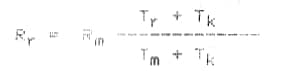
Source: sencamer.gob.ve, COVENIN 3172: 95
Whose parameters are:
- Rr: Value of resistance to the reference temperature.
- Rm: Value of resistance to the temperature at the time of measurement.
- Tr: Reference temperature value (at the end of the test).
- Tk: Temperature constant. For this case is 234.5 ° C (copper).
- Tm: Temperature value at the time of measurement.
Transformers Measurements: open and short circuit tests
With these tests, we can obtain the basic parameters to analyze the behavior of transformers.
With the open circuit test, the power losses are measured due to the hysteresis phenomenon and parasitic current in the core. The procedure of this test consists of applying nominal voltage and measure the low-voltage. For this, we must connect a wattmeter, an ammeter, and a voltmeter while the high side remains an open circuit. The assembly representing the test is shown in image No. 3.
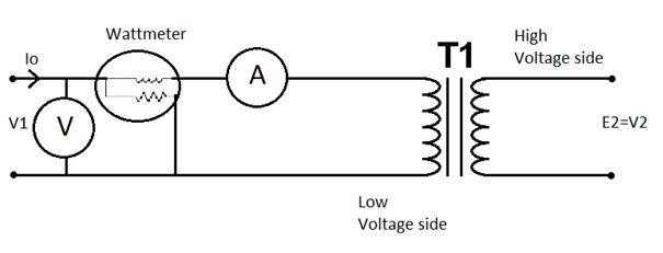
Image N ° 3: Assembly of the circuit for the vacuum test of the transformer | Source: wikipedia
The short circuit test is used to measure the mechanical capability of the transformer to short circuits. The test involves short-circuiting one side of the transformer (preferably the secondary one), while the parameters of voltage, current, and power are measured on the opposite side, such as the one shown in Figure N°4.
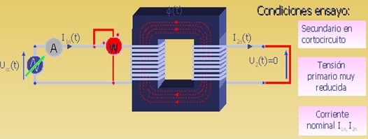
Image N ° 4: Assembly of the circuit for the short-circuit test of the transformer | Source: eltransformadorelectrico
References
[one] http://www.sencamer.gob.ve/sencamer/normas/3540-02.pdf . COVENIN 3540: 2002.
[two] http://www.sencamer.gob.ve/sencamer/normas/3172-95.pdf . COVENIN 3172: 1995.