 If you are an outsourcing resource, working for an existing electrical substation, you are probably aware of how valuable are the plans or drawings.
Keep reading this article if you want to know how drawings are valuable tools that save time and lives!
It doesn’t matter if your work is to do maintenance, plan expansions, remove, compensate or to implement a new sequence of maneuvers for a specific circuit; the conclusion is the same: Drawings are necessary, and more important yet, they need to be as clear as possible, so no confusion should raise from reading them.
Today we are going to explore an interesting way to exploit the potential of the electrical drawings in substations in the benefits of time and caution measures.
Electrical substation: how to save time?
In an electrical substation, the most important element is the circuit breaker, since it can isolate a circuit when maintenance is needed, trip it when a failure occurs or close it when needed, just to name a few reasons. They come with a control board which allows performing all kinds of commands requested to the manufacturer by the substation, all signals handled are introduced in the drawings.
The second most important elements are the relays, which are devices designed to respond to input conditions in a prescribed manner [1] and they may consist of several relay units, each responsive to a specified input, thus providing the desired overall performance characteristic of the relay. Since relays can be programmed, the electrical diagrams are crucial to understanding what they actually do.
The third important element to be focused on, are the switchgear, switch bays, boards, etc since their mission in a substation is to allocate circuits or very important relays. There could be several distributed across a specific yard, but you should be focused on the one related with all the elements of the circuit that you are studying. Since they handle much information, wiring diagrams are necessary.
Keeping the previous paragraph in mind, there are primary elements in a substation that should be in your head when you are involved with a substation: the circuit breaker, the relays controlling it and the switchgear allocating their signals. Afterward, you could extend your interest in other elements such as the measurement instruments. The electrical drawings will tell you how they are connected and which wires you should look when following a signal path.
Electrical substation: functional schemes
This kind of diagram serves with a primary goal which is to show the wiring between devices for a specific function in a circuit, thus, allowing the reader to understand the complexity to perform a given action. Let me explain myself with the following example:
Figure 1 is part of a larger set of drawings (or sheets) for a given circuit of a substation, this circuit is called =E08 according to the standards they used, a mixture between ABB naming convention [2] and the standard IEC-293 (International Electrotechnical Commission). It shows the relationship between different devices distributed across the appropriated bay to produce the closure of the breaker from that circuit.
These devices are the relays (represented as a set of contacts, inputs, and outputs) and the switchgear (represented as the surrounding rectangle).
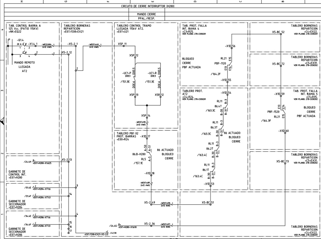
Fig1: A functional scheme, representing the sequence needed in order to perform the closure of the breaker in a circuit of a given substation [CLICK TO ENLARGE]
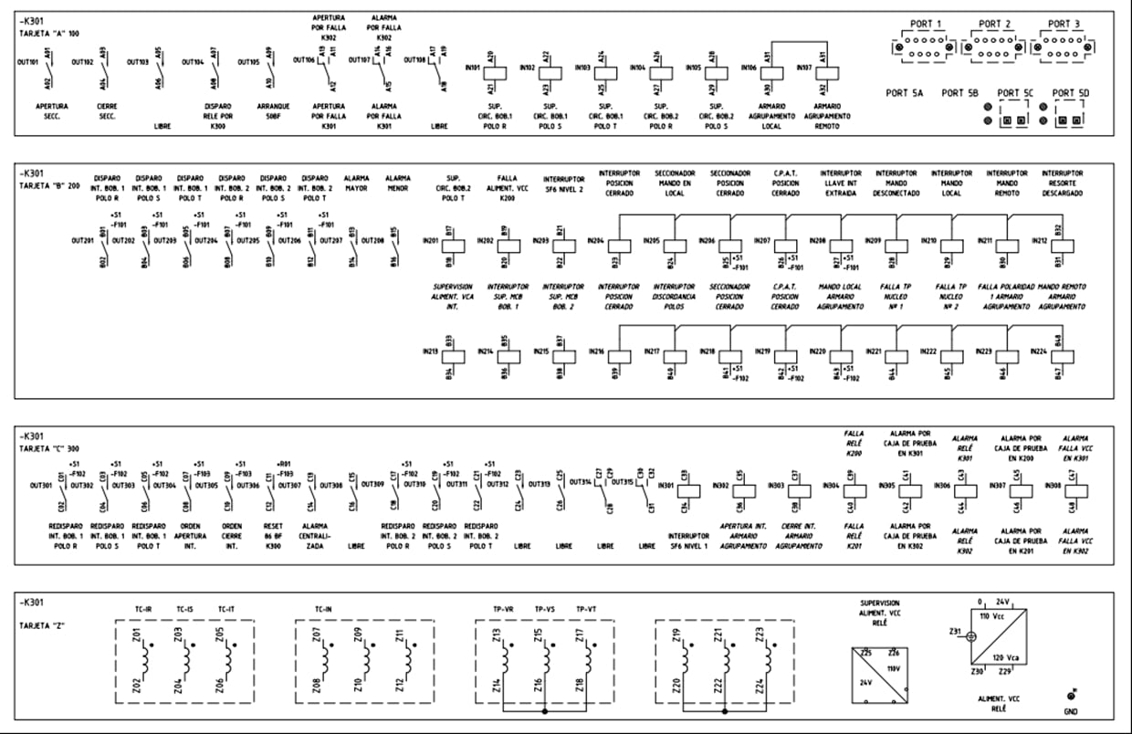
Fig2: A functional scheme, representing the inputs and outputs of a relay [CLICK TO ENLARGE]
Figure 2 is also part of a functional scheme, its purpose is showing all usable I/O contacts of a relay, this implies that a relay serves with several functions when allocated in switchgear.
As it is implied, the purpose here is not to show all the components (I/O) of a particular element, but how do they interact with other devices in order to perform a specific action, like the closure of the circuit breaker (Figure 1). The remaining components are shown in different sheets, again, according to the function they serve.
Electrical substation: basics of functional schemes
The most important thing in these schemes is the designation blocks and their meaning, rather than symbols. As stated in [1], there are four designation blocks (distinguished by prefix signs) available to identify every single device in the installation, they are shown in Figure 3.
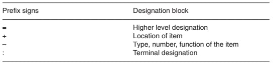
Fig3: Designation blocks and their meanings
Each one them is made of an alphanumeric code according to specific rules, considering things like the bus voltage, the physical arrangement of the circuits and others aspects, all of them dictated by the standards used in the substation.
Going back to Figure 1, the first designation block refers to the circuit of the substation, (like =E07 and =C3), the second refers to the location of the device (like +U21), whether it is switchgear, switch bays, a load center, etc. The third is the device (like -UC1-P), and the last one is the terminal used, where you can find the wires connected.
Any deviation obeys to standards (or other reasons) used in the substation, so, use Figure 3 as a common reference and not as a standard. Some CAD software can help, like ELCAD from autocotec © and Eplan from Eplan ©.
Electrical substation: Final thoughts
Functional diagrams are indeed different of others usable schemes (see Figure 4). Their main purpose is to reduce information according to the particular function you are interested in, this feature saves you from losing time when studying a substation because you focus on a particular circuit or command signal.
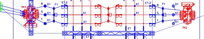
Fig4: An electrical/civil scheme, representing a circuit of a substation just as it is installed on the yard
If you are working directly on the circuits (maintenance, expansion, revision, etc.), it can also spare your life because you will probably not going to make mistakes when attempting to make the right sequence of de-energization.
References
[1] IEEE 100 [7Th ed], The authoritative dictionary of IEEE standards terms.
[2] ABB Switchgear Manual (10th edition), chapter 6: Methods and Aids for planning installations.
What’s your thoughts on this article, Do you feel drawings are key tools in electrical substations?