Introduction
In the preceding article we studied the basics of Earthing and also the basic most Earthing type where the neutral is grounded at source and optionally grounding is done even at customer side.
Besides this, International Standard – IEC 60364 formally defines different types of Earthing arrangements. Let us examine them here in detail.
IEC Standard for Earthing
IEC Standard 60364 specifies a Two Letter Codes to identify type of earthing. It also defines three families of Earthing arrangements.
- The two letter code is based on Source Side – Device Side Earthing.
- The First Letter indicates how the Earthing is done on Source side (Generator / Transformer).
- The Second Letter indicates how the Earthing is done on Device side (place where electricity is consumed at customer premises).
The Letters used are as follows:
T – (French word “Terre” meaning Earth) – It means direct connection of a point to earth
I – It means that either no point is connected to Earth or it is connected via high impedance
N – It means that there is direct connection to neutral at the source of installation which is in turn connected to the ground
Based on a combination of these three letters, there are three families of Earthing arrangements proposed by IEC as below:
- TN Network
- TT Network
- IT Network
TN Network
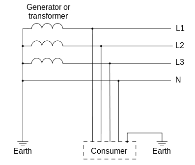
In TN type of earthing system, one of the points of the source side (Generator or Transformer) is connected to earth. This point is usually the star point in a three phase system. The body of the connected electrical device is connected to earth via this earth point on the source side. See fig. below which depicts this:
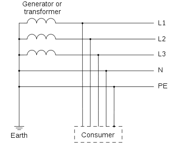
In above diagram:
PE – Acronym for “Protective Earth” – is the conductor that connects the exposed metallic parts of the consumer’s electrical installation to the ground.
N –Also called Neutral. It is the conductor that connects Star point in a 3 phase system to the earth.
There are three sub-types of TN networks as below:
- TN-S
- TN-C
- TN-C-S
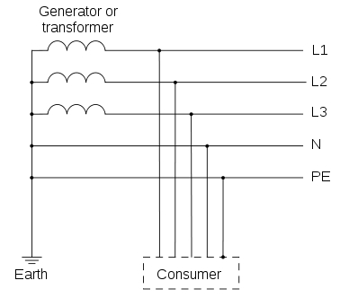
TN-S: In this, separate conductors for Protective Earth (PE) and Neutral run from Consumer’s electrical installation till the source. They are connected together only at the power source.
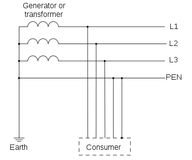
TN-C: In this, there is a combined conductor called PEN (Protective Earth-Neutral) which is connected to earth at the source.
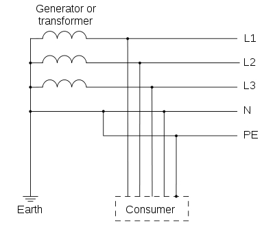
TN-C-S: In this type of earthing, part of the system uses a combined PEN conductor for earthing, whereas for remaining part of the system uses separate conductor for PE and N.
Usually, the combined PEN conductor is used near the source of the system.
TT Network
In TT type of earthing system, consumer employs its own local earth connection in the premises, which is independent of any earth connection at source side.
This type of earthing is preferred in telecommunication applications, because this system is free of any high or low frequency noise that comes through neutral wire connected to the equipment.
IT Network
In IT type of earthing system, there is either no connection to earth at all, or it is done via a high impendence earthing connection.

Country Specific Earthing Standards
UK – Uses Protective Multiple Earthing (PME) – which is a form of TN-C-S type of earthing
Australia / New Zealand – Also uses TN-C-S type of earthing know as Multiple Earth Neutral (MEN) system
USA / Canada – Uses TN-C for the feed from Transformer but uses TN-C-S within the structure at customer premises
France / Japan / Denmark – Uses TT type of earthing and customer must make its own arrangement for its own earthing connection
Very nice post you got there! Thank you!
that’s really helpful.
why should the PEN cable be
firstly connected to the earth point at Load, then to the neutral
point?
Hi,
Can anybody assist me how to get more than 1K ohms betweens 2 earth pits ?
My project is IT distribution system, and I am using step down transformer for 230v power loads, my question is , is it necessary to ground the secondary X2? If yes, why we should ground it and what is that system called ( TN or TT). And is it necessary to use PE conductor cable for external load , such as anti condensation heater, single phase fan, etc).
What is difference between:
– IT with distributed Neutral
&
– IT without distributed Neutral
in single phase system.
Hi all,
Just join this group. Anyway..from my outstanding, earthing system shall be followed the Country Earthing Standard so no doubt on combination of system….
Thank you
that’s great
What is name of this application?
Need advice and reference /please advice
Do we need an external grounding cable which connects outside walls of DB and deck floor or any flooring around.
Modern DB have got a bit different internal system !
There is need to test the nature and type of soil before connecting the neutral to the ground.
Dear Tom, could you tell how many ohms the Code requires and what conditions related to this requirements?
Thank you…
what is the system normally used in Saudi Arabia?
what is the system used in KSA?
I just really want to clarify if the earth for source and device and other metlic and other electrical source, can be combined with the earth lead for the LPS.
I have doubts in it since I didn’t have any known installations from my experiences from the middle east to the south east.
Please enlighten me.
Van
What I am looking for is the type of material to be used for the Earth & the size of the conductor
ie: Material Copper or GI : Conductor size ,75 X 6mm or 50 X 5mm.
Especially For the Neutral of a Transformer in a Residential Gated Colony.
Do hope I receiver a reply to my queries.
In my above message I did not have a Website after sending it a Website was created.
waiting for a reply
Regards
Joe
very nicely explained….