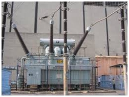
Hi, it’s Steven Mill and today I want to tell you about Measuring The Partial Discharge. Ready?
Transformer routine test is normally conducted to see if there are any partial discharges in the transformer insulation.
What is a partial discharge?
A partial discharge can be described as electrical arcs produced between any of the electrodes in the insulating material of the transformer, which can in turn produce surges between the conductors.
Partial discharges normally occur as a result of little air bubbles left over in the insulating material of the transformer during the manufacturing stage, or at the surface of the insulating media.
What harm can it do?
Partial discharges are electrically very weak, but the thermal energy produced as a result of a partial discharge, is capable of corroding or tearing the insulating medium. Frequent partial discharges can also force the transformers to age prematurely.

Measuring The Partial Discharge (PD)
Partial discharge can be measured by using a calibration transformer. Using this calibration technique the following can be discovered:
- This technique is used to determine if partial discharges are occurring above a certain value, when a predefined voltage is applied to the transformer.
- It also helps in finding out that at what increased voltage is the occurrence of partial discharge taking place and at what voltage a particular partial discharge ceases to exist.
- This test is also used to determine the strength of a particular partial discharge.
Measuring arrangement of a partial discharge in a transformer and its circuit diagram are shown in the figure below:
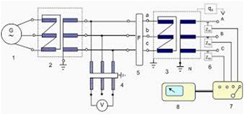
The numbers in the figure above refer to the following components in the measuring system respectively:
- Generator supply
- Transformer supply
- Calibrating transformer
- Measuring circuit coupled with voltage transformer
- Filter
- Impedance Measurement
- Switch
- Oscilloscope
- Calibration generator (qo)
In this circuit, calibration generator produces the necessary predefined load, qo. and measurements at all the terminals of the transformer are taken. This is done by connecting the calibration generator in parallel to the terminals, and the corresponding readings are noted from the different measuring instruments.
After The Calibration Test
After the calibration test is conducted, the calibration generator is removed from the circuit and the transformer is connected to the supply generator. Now the voltage level will be too low. This is called remanance voltage. Also known as the base noise, this voltage value should be less than the partial discharge values that are guaranteed by the manufacturer.
Now the voltage levels are slowly increased to the standard level (as per the specifications given by the manufacturer), and the partial discharge values are noted.
Evaluation
The test is deemed to be successful if the partial discharge values are lower than the pre-defined values noted at the time of the test, or those given by the manufacturer. It should also be seen that there is no sudden spike in the partial discharge value at any terminal, during the testing phase.
In conclusion, a transformer routine test for measuring partial discharge plays an important role in increasing the life of the transformer, eventually increasing the productive hours and decreasing the down time. It is advised that this test is conducted frequently in order to avoid any major blackouts during peak operating periods.
Steven Mill.