Carlos V. is an electrical power systems protection expert. Let him tell you more about distance protection schemes and relay settings applied to multiterminal lines. A second part of this article will be published soon.
Introduction
Multiterminal lines tipically have at least a weak source in one of their terminals as it is shown in figure 1. This condition could negatively affect the performance of the protection systemduring the ocurrence of a faultalong the lines.
It is posible that the weak source terminal might not be able to provide enough current to the fault for the operation of theprotection relay locatedat this terminal, due to the high impedance of the weak source.
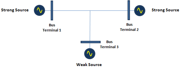
Figure 1. Multiterminal Lines System
Other phenomenons to be considered in multiterminal lines are infeed and outfeed effects. The appearance of an infeed or outfeed current can modify the reach of distance relays.
In this regard, the settings of the protection units must ensure the correct operation, considering all fault current contributions from the location of the relays to the faulted point, minimizing problems related to distance protection overreaching and underreaching.
Therefore it is necessary to implement a protection scheme that allows an adequate operation of the protection relays.
Classification of transmission lines
The lentgh of a transmission line is an important parameter to be considered when its protection scheme is selected.
Theorically, there are three methods typically used to determine the classification of transmission lines according to the lentgh: physical distance, total impedance, and through the Source Impedance Ratio (SIR).
In recent years, protection engineers have adopted the procedure established for the SIR calculation, as the prefered method for the clasification of transmission lines.
The Source Impedance Ratio is defined by the following equation:
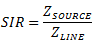
Where:
SIR: Source Impedance Ration
ZSOURCE: Magnitude of the Source Impedance in ohms
ZLINES: Magnitude of the Line Impedance in ohms.
In Table 1, it is described the clasification of transmission lines according to the SIR.
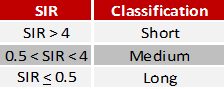
Table 1. Transmission line classification according to the SIR
Protection scheme for multiterminal transmission lines
Setting a distance protection in multiterminal transmission lines is a very difficult task, particularly when a weak source is connected to one end of the lines, as it is featured in figure 1.
However, there is a recommended scheme for tripping the weak source terminal, known as the Weak Infeed and Echo that comprises a Permissive Overreaching Transfer Tripping Scheme (POTT), a Weak Infeed suplement, and an Echo Key Logic (see figure 2).
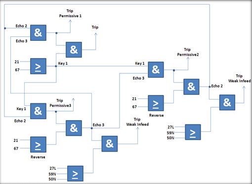
Figure 2. Protection Scheme for the three bus terminal in figure 1.
For a successful sequential circuit breakers tripping, it is required a permissive tripping signal from the strong terminal or the activation of the Weak Infeed Logic.
In addition, the Weak Infeed Logic need other elements to complement distance and directional overcorrent logics. Thus, the logic adds up undervoltage (27L), overvoltage (59N), and Neutral Instantaneous Overcurrent functions to detect low level fault currents. As long as these protection functions might operate during internal and external faults, distance and directional overcurrent functions are used to avoid missopertion of the protection system.
The scheme shown in figure 2, fulfill the tripping premises for a Weak Infeed condition under the following situations:
- A tripping signal is received from the strong terminal, indicating a fault has been detected by the distance relay in forward direction.
- Directional overcurrent relay does not operate in the reverse direction. In other words, there is not any fault behind the weak terminal.
- A voltage drop or a small zero sequence current is sensed on the weak terminal as a consequence of the fault.
On the condition that reverse elements are activated, the Weak Infeed and Echo Logic will be blocked. In tables 2, 3, and 4, recommended protection schemes and communication channels are established for short, medium and long lines, according to IEEE Std. C37.113.
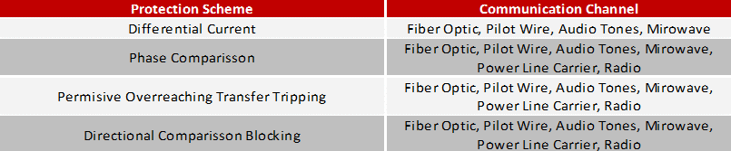
Table 2. Recommended protection scheme for short lines
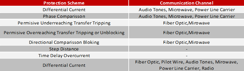
Table 3. Recommended protection scheme for medium lines
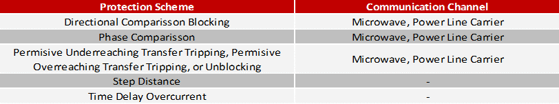
Table 4. Recommended protection scheme for long lines
Conclusion
The classification of transmission lines based on the Source Impedance Ratio allows to implement adequate protection schemes, including the Weak Infeed and Echo Logic, when a multiterminal line comprises weak sources.
Thank you for your attention,
Carlos.
What do you think about this essay? Did it help?
Hello…
I am working on the adjustments for a short medium voltage line (416m), with a RED 670-ABB relay. The phases are segregated bus ducts (phases in an internal conduit, the exterior is a concentric earth).
If a fault occurs in the line, the insulation must be damaged and the current must pass through the air.
I am concerned with the undereach of the distance function because of posible resistance of arc faults.
The impedance of the line is X1 ~ 0.065 Ohms, I believe that any fault can reach a resistance value similar to or greater than this impedance.
Do you know any value or method to obtain the resistance of an MV arc?
How can I take into account this possible resistance to the arch?
Thanks in advance!!