|
In January 2013, some topics remained without response/answer. Maybe you could help the members to solve their problem.
|
Don't forget: it takes 5 minutes to do it and the person asking may become the one to answer YOUR questions in the future!
1. Capacitors
2. State Space Equations for an Oscillator
3. Type of transformer to be used on photovoltaic Systems
4. Searching for a Kill-A-Watt meter
5. Pure sine wave inverter
Thanks in advance for your active contribution to our community

 |
This month we present you one of our forum members: ashok1962 (Ashok Kushwaha) |
Firm director
From Mumbai
Switchboard and switchgear related topics are the subjects which interest him the most
Thinks the community is good even if he’s not visiting frequently
Website: www.iconicinfotech.com
If you would like to become a moderator yourself, you can tell us by mail |
|

|
Armature reaction in DC Generator
|
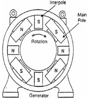 |
| Armature reaction is one of the reasons that causes generated emf in DC Generator to decrease. And this effect is as much important to note as the armature losses and other constant loses like windage and iron losses, because all of them consequently gives us a decreased emf. But compensating winding and commutating poles appreciably decrease this effect and greater part of overall losses in DC Generator is compensated. This topic is focused on one particular aspect of DC Generator. Would you like to know more about DC Generator?
|
MORE>> |

|
Power Factor Correction Equipment: advantages and disadvantages |
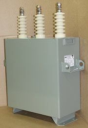 | Normally, the power factor of the whole load on a large generating station is in the region of 0•8 to 0•9. However, sometimes it is lower and in such cases it is generally desirable to take special steps to improve the power factor. This can be achieved by the following equipment: static capacitor, synchronous condenser and phase advancers. What do you think about it? Do you have others advantages or disadvantages in mind? If yes, just add a comment so that we can discuss about it.
|
MORE>> |
|
Stability Factor: K-Factor |
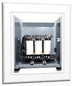 | K-Factor determines the total harmonic current which a transformer can withstand without going beyond its specified temperature threshold limits. Under normal circumstances the value of K-Factor ranges from 1-50. It is the load that determines the K-Factor of the specific transformer. For example in the case of linear loads K-Factor of 1 is used whereas in worst harmonic conditions K-Factor of 50 is advisable. K-Factor rating indicates the tendency of a transformer to supply rated KVA output to a load of specified harmonic content. Did this introduction to K-Factor draw your interest? Feel free to post a comment.
|
MORE>> |
|
 |
|