D.Ros is so crazy about motors that everytime we receive an article from him, we know what it’ll be about. Despite of this, his material is always very interesting and well explained.
For our pleasure, here’s the latest article from him. He chose to make an insight to typical start-up profiles… Let’s read!
Understanding the basics of how synchronous motors work will surely help you take good decisions upon whether or not to use this type of motor, if you rather get a brushless exciter or not, and choose the right start-up method suitable for your application and power system’s availability.
The next thing you should get to know is how a typical start-up looks like, what problems you might encounter and what are the possible solutions to them.
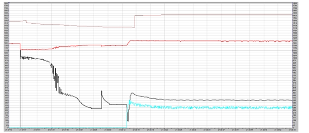
Figure 1: Normal reactor assisted start-up profile of a synchronous motor
Synchronous motors: quick recap
So making a quick recap, the synchronous motor starts as an induction motor, which means it will soak up to seven times the rated current of its stator circuit; this behavior is due to the fact it starts just as an alternate current transformer.
This high current demand will in consequence create a dip in the motor’s bus voltage, however as the electrical current flowing through stator induces the rotor’s circuit, the resulting magnetic field on the rotor starts chasing the stator’s magnetic field that spins at line frequency, thus accelerating the motor and slowly losing the transformer behavior, decreasing the current consumption and recovering the appropriate bus voltage.
The crowbar circuit
So the first concern in the startup of the motor is that as the coils of the rotor’s circuit are induced, as this represents an open coil, since there’s no current flow, its voltage tends to infinity and can become so large that can blow holes in the insulation or cause the coils’ terminals to flashover.
To prevent this, the rotor’s electrical circuit uses a “crowbar” circuit, which basically has a resistor close the rotor’s circuit and allow current flow during startup, therefore avoiding the field’s voltage to rise dangerously.
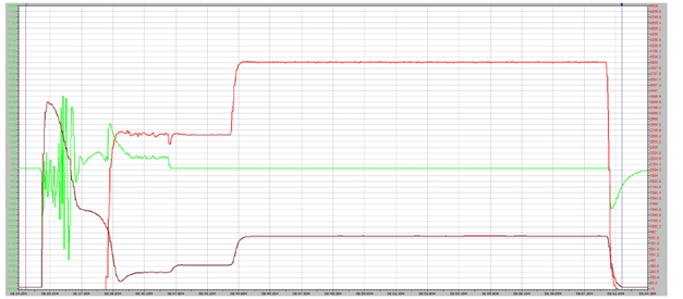
Figure 2: Across-the-line start-up profile of a synchronous motor (Motor’s field induced voltage in green)
This “crowbar” circuit used to be a set of contactors that switch the field’s terminals between the external field supply and the crowbar resistor, yet with the boom of power electronics, this circuit is now predominantly designed with silicon controlled rectifiers (SCRs); furthermore, they’re even inside the assembly in brushless exciters.
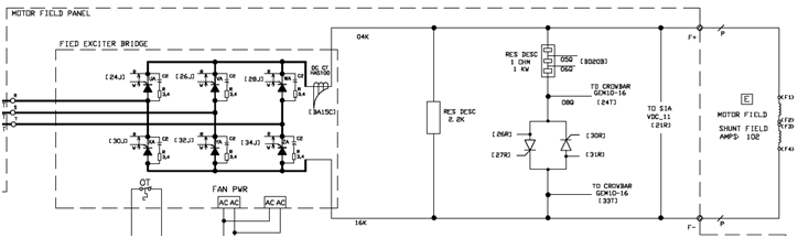
Figure 3: Typical configuration of synchronous motor field circuit with SCR controlled crowbar
The most typical problem with the Crowbar circuit
Since the SCRs in the crowbar circuit are connected back to back to be able to handle the entire span of the alternating current wave, getting them to shut off whenever the motor has been already brought up near synchronous speed or has been successfully synchronized can become a hassle.
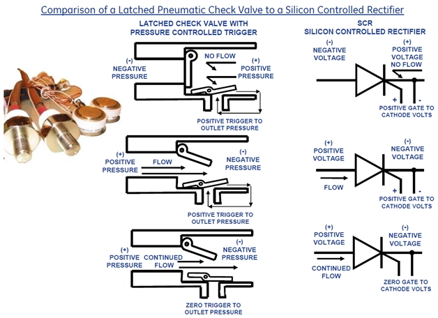
Figure 4: Analogy as to how Silicon-Controlled Rectifiers (SCRs) work
Having in mind how SCRs work, that when turned on they remained latched until the voltage changes polarity, switching from the crowbar resistor to the field’s direct current supply might result in an offset voltage in the SCRs high enough to prevent the AC induced voltage from crossing zero and therefore being unable to turn off and keeping the crowbar resistor in shunt with the motor’s electrical field; in consequence, the resistor heats up trying to dissipate the ample amount of electrical current flowing through the short along the motor’s field windings, ultimately frying itself after a couple of minutes.
Conclusion
Wrapping up, whether the initial commissioning of a synchronous motor is being held or routine maintenance is being done, keep an eye on the field’s crowbar circuit of the motor; watch out for high temperatures in the motor’s field supply cabinet or at the brushless exciter’s assembly.
Fixing this issue usually can be as simple as adjusting the resistors impedance (usually assembled with several step to configure this property) or changing the value of initial direct current supplied by the motor’s DC field exciter supply. Failing to do so, usually ends up in a fried crowbar resistor or even worse in a fried insulation in the rotor’s windings; both implying long downtimes.
See you soon, thanks for reading,
D.Ros.
What do you think about this article? Do you have questions?
This is for direct-on-line (DOL) machines, right?
Can you say how common these are nowadays? I mean converter-fed systems are most likely gaining ground slowly, but then again updating older DOL systems will obviously take time (and money).
Hi Antti,
The first example trend is a soft staring procedure that ends up becoming a (DOL), it just uses a reactor to constraint the current demanded by the motor during startup and afterwards being bypassed to work directly from the line (DOL).
The second example trend is a DOL.
Synchronous machines have and will stay DOL systems because of their high current, however converter-fed systems are used in their field control. What is going on nowadays is that the converter-fed systems have considerably upgraded since the boom of the synchronous machines some decades ago, so much work is being done upgrading this systems that get the most out of this machines.
Regards,
Dante