 Hi everybody, it’s Steven Mill. Hope you’re enjoying your holidays.
I’ve personally been thinking about some topics to deal with on the blog and I thought about the one I’ve published in 2014 (September) about the inspection of voltage drop in conductors.
So today I want to go further and post 4 guidelines in order to help my fellows engineers. Enjoy!
According to NEC, a three percent voltage drop in branched circuits, and five percent voltage drop in feeders connected to branched conductors, will not to create major problems as far as energy efficiency and operation of general circuits is concerned.
But, a voltage drop greater than the indicated percentage (5%), can hamper the life as well as the operational efficiency of electrical circuits and equipment. In an attempt to minimize the voltage drops and keep them below 5%, a few practical guidelines are to be followed.
Below mentioned are the four practical guidelines, following which, voltage drops can be considerably minimized:
- Increasing the number of the conductors or their size
- Reducing the power load
- Decreasing the length of the conductor
- Decreasing the temperature of the conductor
1. Increasing the number of the conductors or their size
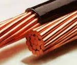 By increasing the number of the conductors or their size, one can successfully reduce the resistance of the conductor. This will in turn result in reduced voltage drops and increased efficiency. This procedure can also considerably lower the overall power losses which are otherwise more in conductors of standard size (as denoted by the general codes).
Also, installing an isolated conductor, which is neutral in nature, for every phase in a branch circuit, can minimize voltage drops caused due to grounding.
2. Reducing the power load
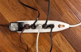 Reducing the power load by decreasing the amount of electrical equipment connected to a circuit can help reduce voltage drops. But, in this case, care should also be taken to see that the number of receptacles connected to each branch circuit is no more than six.
Note: In case of residential complexes, one should always bear in mind that the linear distance between each receptacle should not be more than 50ft, and a minimum of at least one outdoor receptacle should be installed for every house.
It should also be noted that each of these receptacles should be connected to an individual circuit that has a minimum capacity of 12 AWG. This type of arrangement can minimize voltage drops to a greater extent.
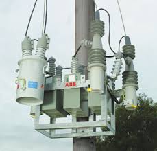
Decreasing the length of the conductor
Decreasing the length of the conductor is yet another alternative to minimize voltage drops. We all know that the length of a conductor is directly proportional to the resistance offered.
Thus, when the length of a conductor is reduced, its resistance to carry power will also reduce, lowering the voltage drops. But the practical problem here is that the circuit lengths are always fixed. Then, how to reduce the length of a conductor?
One can overcome this problem by reducing the length of the conductor (and instead, increasing its diameter) at the design stage of the panel itself One can also overcome this problem by reducing the length of the conductor by installing panels and sub-panels next to the external loads.
This type of panel design is highly recommended, especially, when the electronic equipment to which it is connected is highly sensitive (to sudden voltage drops).
Decreasing the temperature of the conductor
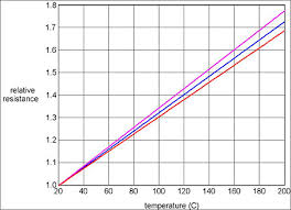
High temperatures in conductors resist the flow of power, leading to voltage drops. Hence, by decreasing the temperature of the conductor, artificially, one can minimize these voltage drops.
It should be noted that, for every one degree raise in temperature, the resistance is increased by 0.3%. It can be measured using the formula:
R2 = R1 [1 + α • (T2 – T1)]
Where,
R1 = Resistance to power flow at Temperature T1
R2 = Resistance to power flow at Temperature T2
And α = co-efficient of electrical resistance of Copper
As the difference between T2 and T1 decreases, the resistance to power ‘α ‘ will also cease to decrease.
Note: By following the above mentioned three guidelines, one can automatically adjust the temperature of the conductor to a desired level.
Conclusion
In order to achieve maximum protection for the electrical equipment as well as domestic electronic appliances, power suppliers need to follow the above mentioned four guidelines as precisely as possible.
This is because, minimizing voltage drops by following above guidelines will not only benefit power suppliers, but will also benefit every common man who is dependent on various kinds of electronic appliances (by increasing their life) for his daily survival.
Thanks for reading,
Steven Mill.
What do you think about these guidelines? Feel free to leave your impressions below!