The distribution is the final stage of carrying electricity from the transmission system to consumers. The distribution substations are connected with transmission lines and the voltage reduced to medium voltage through the transmission systems as shown in Fig1.
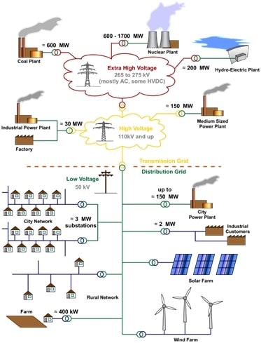
Fig 1.Configuration of electricity network
Through this article, one of the members of the Electrical Engineering Community blog Yasser wants to focus on DC medium voltage stage which ranging between 2KV and 35KV.
DC systems: the reasons of their expansion
The use of DC transmission has widely grown because:
- It reduced total investment costs
- It reduced electric losses
- It has high-quality power supply
- It has good voltage stability
- It has capacity to connect grids with different frequencies
Medium voltage DC configuration
Medium voltage distribution rings usually have a normally open point (NOP) divided into two feeders. The objective of this normally open point is to reduce the effect of faults by limiting the number of affected consumers, but this (NOP) causing indirect grid losses as it obstructs the power flow.
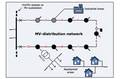
Fig 2.Medium voltage layout
The MVDC can increase the efficiency with a reduction in conversion stages.
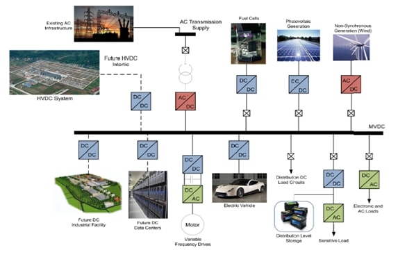
Fig 3. (MVDC) System Architecture
Medium voltage systems: problems & solutions
Harmonics
Reason
Harmonics increased on MV systems because of power factor correction applications. They are generated by residential and commercial customers which have electronic loads and nonlinear loads in the AC drives, rectifiers, induction furnaces and arc furnaces.
It is difficult to reduce the harmonics to acceptable limits when the resonance conditions exist, the overloading of conventional harmonic filters and power factor correction within customer facilities causes this resonance conditions exist on the primary system.
It is preferred to solve the harmonic problem on the primary distribution system than solving it on customer facilities as it is much more economic.
Solution
The capacitors bank are used for power factor correction on distribution system and as voltage support for transmission system. We use the substation capacitor bank as a harmonic filter rather than reduce the size of the compensation further to control the harmonic level and also providing the power factor correction and voltage support.
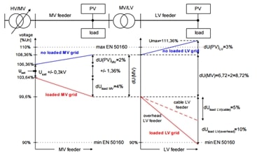
Fig 4. voltage in grids with connected RES
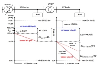
Fig 5. voltage in MV and LV grids without connected RES
Voltage stabilization
Reason
When the PV plants connected into MV and LV in the same part of grid, causing high voltage variance. In addition the renewable energy sources (RES) causes voltage increase 5%UN in relation to LV grid.
Solution
Use the variable controlled HV/MV transformer to control the voltage quickly.
Test the voltage increased or decreased and it is realized in the same time of loaded MV and LV grid to eliminate under voltage or over voltages in the LV distribution grid so it is possible to set variables on the output of HV/MV transformer and the voltage will be in the acceptable range.
HWhat is meant by substation automation?
Today substations need manual switching, collection of data and abnormal condition. As the power systems became more complex so we need to control substations from a faraway point in case of emergency and also to reduce economic costs. SCADA (as shown in Fig6 ) for substations is used to remote control with special wires such as Power-line carrier, microwave radio and fiber optic cables.
The automation makes it easy to detect the faults at the same time and observe the overall system so if any changes are noticed in the system we can improve its performance by:
- Connecting capacitor bank at bus of low voltage
- Making closed loop
- Utilizing over excited generators to injected reactive power at system
- Decrease losses by transmission line chosen
- Control voltage
How to control voltage to improve system performance?
Excitation Control and Voltage Regulation in generating Stations
The generators have excitation and automatic voltage regulation systems to regulate voltage under fault conditions and control the load under steady state condition.
Voltage Control by Tap-changing in transformers
By changing the turns-ratio of transformer, the secondary voltages is changed so it can control the voltage.
The grid will not only be operated with traditional path, but it will need new methods to develop the DC systems with AC network to provide a more efficient systems with bulk powers and less losses.
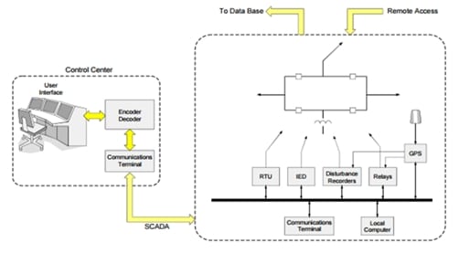
Fig 6. SCADA evaluation
Instrumentation and control (I&C) device of SCADA
- Remote Terminal Unit (RTU): It can transfer and receive data and control commands from devices
- Protective relay: It can sense power system trips and automatically perform suitable control actions.
- Programmable logic controller (PLC): It is a logical control work on command based on master as shown in Fig6.
References of pictures: wikipedia,cigre-usnc.tamu.edu & ecedha.org
Thanks for reading!
Did this back to basics kind of review help?